Generator is a machine that converts mechanical energy into electrical energy. It works based on principle of faraday law of electromagnetic induction. The faradays law states that whenever a conductor is placed in a varying magnetic field, EMF is induced and this induced EMF is equal to the rate of change of flux linkages. This EMF can be generated when there is either relative space or relative time variation between the conductor and magnetic field. So the important elements of a generator are:
• Magnetic field
• Motion of conductor in magnetic field
MAIN COMPONENTS OF A GENERATOR
A description of the main components of a generator is given below.
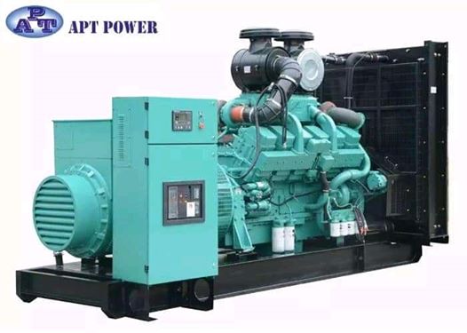
(1) Engine
The engine is the source of the input mechanical energy to the generator. The size of the engine is directly proportional to the maximum power output the generator can supply. There are several factors that you need to keep in mind while assessing the engine of your generator. The manufacturer of the engine should be consulted to obtain full engine operation specifications and maintenance schedules.
(a) Type of Fuel Used – Generator engines operate on a variety of fuels such as diesel, gasoline, propane (in liquefied or gaseous form), or natural gas
(b) Overhead Valve (OHV) Engines versus non-OHV Engines – OHV engines differ from other engines in that the intake and exhaust valves of the engine are located in the head of the engine’s cylinder as opposed to being mounted on the engine block. OHV engines have several advantages over other engines such as:
• Compact design
• Simpler operation mechanism
• Durability
• User-friendly in operations
• Low noise during operations
• Low emission levels
However, OHV-engines are also more expensive than other engines.
(c) Cast Iron Sleeve (CIS) in Engine Cylinder – The CIS is a lining in the cylinder of the engine. It reduces wear and tear, and ensures durability of the engine.
(2) Alternator
The alternator, also known as the ‘genhead’, is the part of the generator that produces the electrical output from the mechanical input supplied by the engine. It contains an assembly of stationary and moving parts encased in a housing. The components work together to cause relative movement between the magnetic and electric fields, which in turn generates electricity.
(a) Stator – This is the stationary component. It contains a set of electrical conductors wound in coils over an iron core.
(b) Rotor / Armature – This is the moving component that produces a rotating magnetic field in any one of the following three ways:
(i) By induction – These are known as brushless alternators and are usually used in large generators.
(ii) By permanent magnets – This is common in small alternator units.
(iii) By using an exciter – An exciter is a small source of direct current (DC) that energizes the rotor through an assembly of conducting slip rings and brushes.
The rotor generates a moving magnetic field around the stator, which induces a voltage difference between the windings of the stator. This produces the alternating current (AC) output of the generator.
The following are the factors that you need to keep in mind while assessing the alternator of a generator:
(a) Metal versus Plastic Housing – An all-metal design ensures durability of the alternator. Plastic housings get deformed with time and cause the moving parts of the alternator to be exposed. This increases wear and tear and more importantly, is hazardous to the user.
(b) Ball Bearings versus Needle Bearings – Ball bearings are preferred and last longer.
(c) Brushless Design – An alternator that does not use brushes requires less maintenance and also produces cleaner power.
(3) Fuel System
The fuel tank usually has sufficient capacity to keep the generator operational for 6 to 8 hours on an average. In the case of small generator units, the fuel tank is a part of the generator’s skid base or is mounted on top of the generator frame. Common features of the fuel system include the following:
(a) Pipe connection from fuel tank to engine – The supply line directs fuel from the tank to the engine and the return line directs fuel from the engine to the tank.
(b) Ventilation pipe for fuel tank – The fuel tank has a ventilation pipe to prevent the build-up of pressure or vacuum during refilling and drainage of the tank. When you refill the fuel tank, ensure metal-to-metal contact between the filler nozzle and the fuel tank to avoid sparks.
(c) Overflow connection from fuel tank to the drain pipe – This is required so that any overflow during refilling of the tank does not cause spillage of the liquid on the generator set.
(d) Fuel pump – This transfers fuel from the main storage tank to the day tank. The fuel pump is typically electrically operated.
(e) Fuel Water Separator / Fuel Filter – This separates water and foreign matter from the liquid fuel to protect other components of the generator from corrosion and contamination.
(f) Fuel Injector – This atomizes the liquid fuel and sprays the required amount of fuel into the combustion chamber of the engine.
(4) Voltage Regulator
As the name implies, this component regulates the output voltage of the generator. The mechanism is described below against each component that plays a part in the cyclical process of voltage regulation.
(1) Voltage Regulator: Conversion of AC Voltage to DC Current – The voltage regulator takes up a small portion of the generator’s output of AC voltage and converts it into DC current. The voltage regulator then feeds this DC current to a set of secondary windings in the stator, known as exciter windings.
(2) Exciter Windings: Conversion of DC Current to AC Current – The exciter windings now function similar to the primary stator windings and generate a small AC current. The exciter windings are connected to units known as rotating rectifiers.
(3) Rotating Rectifiers: Conversion of AC Current to DC Current – These rectify the AC current generated by the exciter windings and convert it to DC current. This DC current is fed to the rotor / armature to create an electromagnetic field in addition to the rotating magnetic field of the rotor / armature.
(4) Rotor / Armature: Conversion of DC Current to AC Voltage – The rotor / armature now induces a larger AC voltage across the windings of the stator, which the generator now produces as a larger output AC voltage.
This cycle continues till the generator begins to produce output voltage equivalent to its full operating capacity. As the output of the generator increases, the voltage regulator produces less DC current. Once the generator reaches full operating capacity, the voltage regulator attains a state of equilibrium and produces just enough DC current to maintain the generator’s output at full operating level.
(5) Cooling & Exhaust Systems
(a) Cooling System
Continuous usage of the generator causes its various components to get heated up. It is essential to have a cooling and ventilation system to withdraw heat produced in the process.
Raw/fresh water is sometimes used as a coolant for generators, but these are mostly limited to specific situations like small generators in city applications or very large units over 2250 kW and above. Hydrogen is sometimes used as a coolant for the stator windings of large generator units since it is more efficient at absorbing heat than other coolants. Hydrogen removes heat from the generator and transfers it through a heat exchanger into a secondary cooling circuit that contains de-mineralized water as a coolant.
(b) Exhaust System
Exhaust fumes emitted by a generator are just like exhaust from any other diesel or gasonline engine and contain highly toxic chemicals that need to be properly managed. Hence, it is essential to install an adequate exhaust system to dispose of the exhaust gases.
Exhaust pipes are usually made of cast iron, wrought iron, or steel. These need to be freestanding and should not be supported by the engine of the generator. Exhaust pipes are usually attached to the engine using flexible connectors to minimize vibrations and prevent damage to the generator’s exhaust system.
(6) Lubricating System
Since the generator comprises moving parts in its engine, it requires lubrication to ensure durability and smooth operations for a long period of time. The generator’s engine is lubricated by oil stored in a pump.
(7) Battery Charger
The start function of a generator is battery-operated. The battery charger keeps the generator battery charged by supplying it with a precise ‘float’ voltage. If the float voltage is very low, the battery will remain undercharged. If the float voltage is very high, it will shorten the life of the battery. Battery chargers are usually made of stainless steel to prevent corrosion. They are also fully automatic and do not require any adjustments to be made or any settings to be changed. The DC output voltage of the battery charger is set at 2.33 Volts per cell, which is the precise float voltage for lead acid batteries. The battery charger has an isolated DC voltage output that does interfere with the normal functioning of the generator.
(8) Control Panel
This is the user interface of the generator and contains provisions for electrical outlets and controls. The following article provides further details regarding the generator control panel. Different manufacturers have varied features to offer in the control panels of their units. Some of these are mentioned below.
(a) Electric start and shut-down – Auto start control panels automatically start your generator during a power outage, monitor the generator while in operation, and automatically shut down the unit when no longer required.
(b) Engine gauges – Different gauges indicate important parameters such as oil pressure, temperature of coolant, battery voltage, engine rotation speed, and duration of operation. Constant measurement and monitoring of these parameters enables built-in shut down of the generator when any of these cross their respective threshold levels.
(c) Generator gauges – The control panel also has meters for the measurement of output current and voltage, and operating frequency.
(d) Other controls – Phase selector switch, frequency switch, and engine control switch (manual mode, auto mode) among others.
(9) Main Assembly / Frame
All generators, portable or stationary, have customized housings that provide a structural base support. The frame also allows for the generated to be earthed for safety.
WORKING PRINCIPLES OF GENERATORS:
Generators are basically coils of electric conductors, normally copper wire, that are tightly wound onto a metal core and are mounted to turn around inside an exhibit of large magnets. An electric conductor moves through a magnetic field, the magnetism will interface with the electrons in the conductor to induce a flow of electrical current inside it.
The conductor coil and its core are called the armature, connecting the armature to the shaft of a mechanical power source, for example a motor, the copper conductor can turn at exceptionally increased speed over the magnetic field.
The point when the generator armature first starts to turn, then there is a weak magnetic field in the iron pole shoes. As the armature turns, it starts to raise voltage. Some of this voltage is making on the field windings through the generator regulator. This impressed voltage builds up stronger winding current, raises the strength of the magnetic field. The expanded field produces more voltage in the armature. This, in turn, make more current in the field windings, with a resultant higher armature voltage. At this time the signs of the shoes depended on the direction of flow of current in the field winding. The opposite signs will give current to flow in wrong direction.
TYPES OF GENERATORS
The generators are classified into two types.
1. AC generators
2. DC generators
1. AC GENERATORS
These are also called as alternators. It is the most important means of producing electrical power in many of the places since now days all the consumers are using AC. It works based on principle of the electromagnetic induction. These are of two types one is induction generator and other one is synchronous generator. The induction generator requires no separate DC excitation, regulator controls, frequency control or governor. This concept takes place when conductor coils turn in a magnetic field actuating a current and a voltage. The generators should run at a consistent speed to convey a stable AC voltage, even no load is accessible.
Synchronous generators are large size generators mainly used in power plants. These may be rotating field type or rotating armature type. In rotating armature type, armature is at rotor and field is at stator. Rotor armature current is taken through slip rings and brushes. These are limited due to high wind losses. These are used for low power output applications. Rotating field type of alternator is widely used because of high power generation capability and absence of slip rings and brushes.
It can be either 3 phase or two phase generators. A two-phase alternator produces two completely separate voltages. Each voltage may be considered as a single-phase voltage. Each is generated voltage completely independent of the other. The three-phase alternator has three single-phase windings spaced such that the voltage induced in any one phase is displaced by 120º from the other two. These can be connected either delta or wye connections. In Delta Connection each coil end is connected together to form a closed loop. A Delta Connection appears like the Greek Letter Delta (Δ). In Wye Connection one end of each coil connected together and the other end of each coil left open for external connections. A Wye Connection appears as the letter Y.
These generators are packaged with an engine or turbine to be used as a motor-generator set and used in applications like naval, oil and gas extraction, mining machinery, wind power plants etc.
Main parts of AC Generator (Alternator)
Obviously, consists of stator and rotor. But, the unlike other machines, in most of the alternators, field exciters are rotating and the armature coil is stationary.
Stator:
Unlike in DC machine stator of an alternator is not meant to serve path for magnetic flux. Instead, the stator is used for holding armature winding. The stator core is made up of lamination of steel alloys or magnetic iron, to minimize the eddy current losses.
Why Armature Winding Is Stationary in an Alternator?
At high voltages, it easier to insulate stationary armature winding, which may be as high as 30 kV or more.
The high voltage output can be directly taken out from the stationary armature. Whereas, for a rotary armature, there will be large brush contact drop at higher voltages, also the sparking at the brush surface will occur.
Field exciter winding is placed in rotor, and the low dc voltage can be transferred safely.
The armature winding can be braced well, so as to prevent deformation caused by the high centrifugal force.
Rotor:
There are two types of rotor used in an AC generator / alternator:
1. Salient pole type: Salient pole type rotor is used in low and medium speed alternators. Construction of AC generator of salient pole type rotor is shown in the figure above. This type of rotor consists of large number of projected poles (called salient poles), bolted on a magnetic wheel. These poles are also laminated to minimize the eddy current losses. Alternators featuring this type of rotor are large in diameters and short in axial length.
2. Cylindrical type: Cylindrical type rotors are used in high speed alternators, especially in turbo alternators. This type of rotor consists of a smooth and solid steel cylinder havingg slots along its outer periphery. Field windings are placed in these slots.
The DC supply is given to the rotor winding through the slip rings and and brushes arrangement.
Advantages of AC Generator
• These Generators are generally maintenance free, because of absence of brushes.
• Easily step up and step down through transformers.
• Transmission link size might be thinner because of step up feature
• Size of the generator relatively smaller than DC machine
• Losses are relatively less than DC machine
• These Generator breakers are relatively smaller than DC breakers
• For the large part, an AC motor has a very simple structure, because the only moving part it has is the rotor. for the large part, an AC motor has a very simple structure, because the only moving part it has is the rotor.
• This also makes it easier to maintain these generators.
• They have a quiet operation.
• Cost of ownership is lower.
• Longer lifespan compared to DC motors that have a commutator and carbon brushes that wear out over a period of time. These require regular replacement through the life of the system.
• AC motors don’t have a smell that’s very typical of DC motors; in the latter, this is caused by components that are more prone to friction.
• An AC generator allows users to covert its current to other voltages with the use of transformers; and these are compatible only with an AC generator and not with a DC generator.
• This also makes it easier to maintain these generators.
• They have a quiet operation.
• Cost of ownership is lower.
Disadvantages of AC Generator
• These systems require additional insulation because of the greater voltages needed to supply a fixed level of power.
• This poses a challenge when it comes to handling AC generators in a safe manner.
• Working with Alternating current systems has some distinct risks and difficulties compared to what can be expected from DC motors.
• While the use of a transformer is an advantage in AC systems, to a certain degree that can prove to be a limitation as well. This is because the motors then require a specific design which becomes a hindrance to a higher voltage discharge generated from one side. But since there is no other efficient method of generating high voltages, it becomes necessary to utilise transformers to ease the long-distance transmissions. These transmissions occur as soon as the lower voltage converts to the required higher levels.
• Aside from this, Alternating Current power is more prone to overheating and sparks because it produces higher currents and this particular phenomenon can result in electrical shock as well as fires. The latter can cause a significant amount of damage to property and pose a threat to lives as well.
• In addition to all these risks, an AC generator isn’t as durable as a DC generator.
2. DC GENERATORS
DC generator is typically found in off-grid applications. These generators give a seamless power supply directly into electric storage devices and DC power grids without novel equipment. The stored power is carries to loads through dc-ac converters. The DC generators could be controlled back to an unmoving speed as batteries tend to be stimulating to recover considerably more fuel.
A dc generator is an electrical machine which converts mechanical energy into direct current electricity. This energy conversion is based on the principle of production of dynamically induced emf. This article outlines basic construction and working of a DC generator.
Construction of DC Machine:
Note: A DC generator can be used as a DC motor without any constructional changes and vice versa is also possible. Thus, a DC generator or a DC motor can be broadly termed as a DC machine. These basic constructional details are also valid for the construction of a DC motor. Hence, let’s call this point as construction of a DC machine instead of just ‘construction of a dc generator’.
A DC machine consists of two basic parts; stator and rotor. Basic constructional parts of a DC machine are described below.
1. Yoke: The outer frame of a dc machine is called as yoke. It is made up of cast iron or steel. It not only provides mechanical strength to the whole assembly but also carries the magnetic flux produced by the field winding.
2. Poles and pole shoes: Poles are joined to the yoke with the help of bolts or welding. They carry field winding and pole shoes are fastened to them. Pole shoes serve two purposes;
(i) they support field coils and
(ii) spread out the flux in air gap uniformly.
3. Field winding: They are usually made of copper. Field coils are former wound and placed on each pole and are connected in series. They are wound in such a way that, when energized, they form alternate North and South poles.
4. Armature core: Armature core is the rotor of a dc machine. It is cylindrical in shape with slots to carry armature winding. The armature is built up of thin laminated circular steel disks for reducing eddy current losses. It may be provided with air ducts for the axial air flow for cooling purposes. Armature is keyed to the shaft.
5. Armature winding: It is usually a former wound copper coil which rests in armature slots. The armature conductors are insulated from each other and also from the armature core. Armature winding can be wound by one of the two methods; lap winding or wave winding. Double layer lap or wave windings are generally used. A double layer winding means that each armature slot will carry two different coils.
6. Commutator and brushes: Physical connection to the armature winding is made through a commutator-brush arrangement. The function of a commutator, in a dc generator, is to collect the current generated in armature conductors. Whereas, in case of a dc motor, commutator helps in providing current to the armature conductors. A commutator consists of a set of copper segments which are insulated from each other. The number of segments is equal to the number of armature coils. Each segment is connected to an armature coil and the commutator is keyed to the shaft. Brushes are usually made from carbon or graphite. They rest on commutator segments and slide on the segments when the commutator rotates keeping the physical contact to collect or supply the current.
Working Principle of DC Generator:
According to Faraday’s laws of electromagnetic induction, whenever a conductor is placed in a varying magnetic field (OR a conductor is moved in a magnetic field), an emf (electromotive force) gets induced in the conductor. The magnitude of induced emf can be calculated from the emf equation of dc generator. If the conductor is provided with a closed path, the induced current will circulate within the path. In a DC generator, field coils produce an electromagnetic field and the armature conductors are rotated into the field. Thus, an electromagnetically induced emf is generated in the armature conductors. The direction of induced current is given by Fleming’s right hand rule.
Need of a Split ring commutator:
According to Fleming’s right hand rule, the direction of induced current changes whenever the direction of motion of the conductor changes. Let’s consider an armature rotating clockwise and a conductor at the left is moving upward. When the armature completes a half rotation, the direction of motion of that particular conductor will be reversed to downward. Hence, the direction of current in every armature conductor will be alternating. If you look at the above figure, you will know how the direction of the induced current is alternating in an armature conductor. But with a split ring commutator, connections of the armature conductors also get reversed when the current reversal occurs. And therefore, we get unidirectional current at the terminals.
Types of DC Generator:
Each DC machine can act as a generator or a motor. Hence, this classification is valid for both DC generators and DC motors. DC machines are usually classified on the basis of their field excitation method.
This makes two broad categories of dc machines;
(I) Separately excited and
(II) Self-excited.
(I)Separately excited DC machines:
In separately excited dc machines, the field winding is supplied from a separate power source. That means the field winding is electrically separated from the armature circuit. Separately excited DC generators are not commonly used because they are relatively expensive due to the requirement of an additional power source or circuitry. They are used in laboratories for research work, for accurate speed control of DC motors with Ward-Leonard system and in few other applications where self-excited DC generators are unsatisfactory. In this type, the stator field flux may also be provided with the help of permanent magnets (such as in permanent magnet DC motors).
(II)Self-excited DC machines:
In this type, field winding and armature winding are interconnected in various ways to achieve a wide range of performance characteristics (for example, field winding in series or parallel with the armature winding).
In a self-excited type of DC generator, the field winding is energized by the current produced by themselves. A small amount of flux is always present in the poles due to the residual magnetism. So, initially, current induces in the armature conductors of a dc generator only due to the residual magnetism. The field flux gradually increases as the induced current starts flowing through the field winding.
Self-excited machines can be further classified as :
1. Series wound dc machines –
In this type, field winding is connected in series with the armature winding. Therefore, the field winding carries whole of the load current (armature current). That is why series winding is designed with few turns of thick wire and the resistance is kept very low (about 0.5 Ohm).
2. Shunt wound dc machines –
Here, field winding is connected in parallel with the armature winding. Hence, the full voltage is applied across the field winding. Shunt winding is made with a large number of turns and the resistance is kept very high (about 100 Ohm). It takes only small current which is less than 5% of the rated armature current.
Applications
* DC shunt wound generators are used for lighting purposes.
* Used to charge the battery.
* Providing excitation to the alternators.
3. Compound wound dc machines –
In this type, there are two sets of field winding. One is connected in series and the other is connected in parallel with the armature winding. Compound wound machines are further divided as –
* Short shunt – field winding is connected in parallel with only the armature winding
* Long shunt – field winding is connected in parallel with the combination of series field winding and armature winding
Applications of DC Generators
The applications of the various types of DC Generators are as follows: –
Separately Excited DC Generators
* Separately excited DC Generators are used in laboratories for testing as they have a wide range of voltage output.
* Used as a supply source of DC motors.
Shunt wound Generators
* DC shunt wound generators are used for lighting purposes.
* Used to charge the battery.
* Providing excitation to the alternators.
Series Wound Generators
* DC series wound generators are used in DC locomotives for regenerative braking for providing field excitation current.
* Used as a booster in distribution networks.
* Over compounded cumulative generators are used in lighting and heavy power supply.
* Flat compounded generators are used in offices, hotels, homes, schools, etc.
* Deferentially compounded generators are mainly used for arc welding purpose.
Advantages of DC Generator:
• Mainly DC machines have the wide variety of operating characteristics which can be obtained by selection of the method of excitation of the field winding.
• The output voltage can be smoothed by regularly arranging the coils around the armature. This leads to less fluctuations which is desirable for some steady state applications.
• No shielding need for radiation so cable cost will be less as compared to AC.GENERATORS: WORKING PRINCIPLE, CLASSIFICATION AND APPLICATIONS
Generator is a machine that converts mechanical energy into electrical energy. It works based on principle of faraday law of electromagnetic induction. The faradays law states that whenever a conductor is placed in a varying magnetic field, EMF is induced and this induced EMF is equal to the rate of change of flux linkages. This EMF can be generated when there is either relative space or relative time variation between the conductor and magnetic field. So the important elements of a generator are:
• Magnetic field
• Motion of conductor in magnetic field
MAIN COMPONENTS OF A GENERATOR
A description of the main components of a generator is given below.
(1) Engine
The engine is the source of the input mechanical energy to the generator. The size of the engine is directly proportional to the maximum power output the generator can supply. There are several factors that you need to keep in mind while assessing the engine of your generator. The manufacturer of the engine should be consulted to obtain full engine operation specifications and maintenance schedules.
(a) Type of Fuel Used – Generator engines operate on a variety of fuels such as diesel, gasoline, propane (in liquefied or gaseous form), or natural gas
(b) Overhead Valve (OHV) Engines versus non-OHV Engines – OHV engines differ from other engines in that the intake and exhaust valves of the engine are located in the head of the engine’s cylinder as opposed to being mounted on the engine block. OHV engines have several advantages over other engines such as:
• Compact design
• Simpler operation mechanism
• Durability
• User-friendly in operations
• Low noise during operations
• Low emission levels
However, OHV-engines are also more expensive than other engines.
(c) Cast Iron Sleeve (CIS) in Engine Cylinder – The CIS is a lining in the cylinder of the engine. It reduces wear and tear, and ensures durability of the engine.
(2) Alternator
The alternator, also known as the ‘genhead’, is the part of the generator that produces the electrical output from the mechanical input supplied by the engine. It contains an assembly of stationary and moving parts encased in a housing. The components work together to cause relative movement between the magnetic and electric fields, which in turn generates electricity.
(a) Stator – This is the stationary component. It contains a set of electrical conductors wound in coils over an iron core.
(b) Rotor / Armature – This is the moving component that produces a rotating magnetic field in any one of the following three ways:
(i) By induction – These are known as brushless alternators and are usually used in large generators.
(ii) By permanent magnets – This is common in small alternator units.
(iii) By using an exciter – An exciter is a small source of direct current (DC) that energizes the rotor through an assembly of conducting slip rings and brushes.
The rotor generates a moving magnetic field around the stator, which induces a voltage difference between the windings of the stator. This produces the alternating current (AC) output of the generator.
The following are the factors that you need to keep in mind while assessing the alternator of a generator:
(a) Metal versus Plastic Housing – An all-metal design ensures durability of the alternator. Plastic housings get deformed with time and cause the moving parts of the alternator to be exposed. This increases wear and tear and more importantly, is hazardous to the user.
(b) Ball Bearings versus Needle Bearings – Ball bearings are preferred and last longer.
(c) Brushless Design – An alternator that does not use brushes requires less maintenance and also produces cleaner power.
(3) Fuel System
The fuel tank usually has sufficient capacity to keep the generator operational for 6 to 8 hours on an average. In the case of small generator units, the fuel tank is a part of the generator’s skid base or is mounted on top of the generator frame. Common features of the fuel system include the following:
(a) Pipe connection from fuel tank to engine – The supply line directs fuel from the tank to the engine and the return line directs fuel from the engine to the tank.
(b) Ventilation pipe for fuel tank – The fuel tank has a ventilation pipe to prevent the build-up of pressure or vacuum during refilling and drainage of the tank. When you refill the fuel tank, ensure metal-to-metal contact between the filler nozzle and the fuel tank to avoid sparks.
(c) Overflow connection from fuel tank to the drain pipe – This is required so that any overflow during refilling of the tank does not cause spillage of the liquid on the generator set.
(d) Fuel pump – This transfers fuel from the main storage tank to the day tank. The fuel pump is typically electrically operated.
(e) Fuel Water Separator / Fuel Filter – This separates water and foreign matter from the liquid fuel to protect other components of the generator from corrosion and contamination.
(f) Fuel Injector – This atomizes the liquid fuel and sprays the required amount of fuel into the combustion chamber of the engine.
(4) Voltage Regulator
As the name implies, this component regulates the output voltage of the generator. The mechanism is described below against each component that plays a part in the cyclical process of voltage regulation.
(1) Voltage Regulator: Conversion of AC Voltage to DC Current – The voltage regulator takes up a small portion of the generator’s output of AC voltage and converts it into DC current. The voltage regulator then feeds this DC current to a set of secondary windings in the stator, known as exciter windings.
(2) Exciter Windings: Conversion of DC Current to AC Current – The exciter windings now function similar to the primary stator windings and generate a small AC current. The exciter windings are connected to units known as rotating rectifiers.
(3) Rotating Rectifiers: Conversion of AC Current to DC Current – These rectify the AC current generated by the exciter windings and convert it to DC current. This DC current is fed to the rotor / armature to create an electromagnetic field in addition to the rotating magnetic field of the rotor / armature.
(4) Rotor / Armature: Conversion of DC Current to AC Voltage – The rotor / armature now induces a larger AC voltage across the windings of the stator, which the generator now produces as a larger output AC voltage.
This cycle continues till the generator begins to produce output voltage equivalent to its full operating capacity. As the output of the generator increases, the voltage regulator produces less DC current. Once the generator reaches full operating capacity, the voltage regulator attains a state of equilibrium and produces just enough DC current to maintain the generator’s output at full operating level.
(5) Cooling & Exhaust Systems
(a) Cooling System
Continuous usage of the generator causes its various components to get heated up. It is essential to have a cooling and ventilation system to withdraw heat produced in the process.
Raw/fresh water is sometimes used as a coolant for generators, but these are mostly limited to specific situations like small generators in city applications or very large units over 2250 kW and above. Hydrogen is sometimes used as a coolant for the stator windings of large generator units since it is more efficient at absorbing heat than other coolants. Hydrogen removes heat from the generator and transfers it through a heat exchanger into a secondary cooling circuit that contains de-mineralized water as a coolant.
(b) Exhaust System
Exhaust fumes emitted by a generator are just like exhaust from any other diesel or gasonline engine and contain highly toxic chemicals that need to be properly managed. Hence, it is essential to install an adequate exhaust system to dispose of the exhaust gases.
Exhaust pipes are usually made of cast iron, wrought iron, or steel. These need to be freestanding and should not be supported by the engine of the generator. Exhaust pipes are usually attached to the engine using flexible connectors to minimize vibrations and prevent damage to the generator’s exhaust system.
(6) Lubricating System
Since the generator comprises moving parts in its engine, it requires lubrication to ensure durability and smooth operations for a long period of time. The generator’s engine is lubricated by oil stored in a pump.
(7) Battery Charger
The start function of a generator is battery-operated. The battery charger keeps the generator battery charged by supplying it with a precise ‘float’ voltage. If the float voltage is very low, the battery will remain undercharged. If the float voltage is very high, it will shorten the life of the battery. Battery chargers are usually made of stainless steel to prevent corrosion. They are also fully automatic and do not require any adjustments to be made or any settings to be changed. The DC output voltage of the battery charger is set at 2.33 Volts per cell, which is the precise float voltage for lead acid batteries. The battery charger has an isolated DC voltage output that does interfere with the normal functioning of the generator.
(8) Control Panel
This is the user interface of the generator and contains provisions for electrical outlets and controls. The following article provides further details regarding the generator control panel. Different manufacturers have varied features to offer in the control panels of their units. Some of these are mentioned below.
(a) Electric start and shut-down – Auto start control panels automatically start your generator during a power outage, monitor the generator while in operation, and automatically shut down the unit when no longer required.
(b) Engine gauges – Different gauges indicate important parameters such as oil pressure, temperature of coolant, battery voltage, engine rotation speed, and duration of operation. Constant measurement and monitoring of these parameters enables built-in shut down of the generator when any of these cross their respective threshold levels.
(c) Generator gauges – The control panel also has meters for the measurement of output current and voltage, and operating frequency.
(d) Other controls – Phase selector switch, frequency switch, and engine control switch (manual mode, auto mode) among others.
(9) Main Assembly / Frame
All generators, portable or stationary, have customized housings that provide a structural base support. The frame also allows for the generated to be earthed for safety.
WORKING PRINCIPLES OF GENERATORS:
Generators are basically coils of electric conductors, normally copper wire, that are tightly wound onto a metal core and are mounted to turn around inside an exhibit of large magnets. An electric conductor moves through a magnetic field, the magnetism will interface with the electrons in the conductor to induce a flow of electrical current inside it.
The conductor coil and its core are called the armature, connecting the armature to the shaft of a mechanical power source, for example a motor, the copper conductor can turn at exceptionally increased speed over the magnetic field.
The point when the generator armature first starts to turn, then there is a weak magnetic field in the iron pole shoes. As the armature turns, it starts to raise voltage. Some of this voltage is making on the field windings through the generator regulator. This impressed voltage builds up stronger winding current, raises the strength of the magnetic field. The expanded field produces more voltage in the armature. This, in turn, make more current in the field windings, with a resultant higher armature voltage. At this time the signs of the shoes depended on the direction of flow of current in the field winding. The opposite signs will give current to flow in wrong direction.
TYPES OF GENERATORS
The generators are classified into two types.
1. AC generators
2. DC generators
1. AC GENERATORS
These are also called as alternators. It is the most important means of producing electrical power in many of the places since now days all the consumers are using AC. It works based on principle of the electromagnetic induction. These are of two types one is induction generator and other one is synchronous generator. The induction generator requires no separate DC excitation, regulator controls, frequency control or governor. This concept takes place when conductor coils turn in a magnetic field actuating a current and a voltage. The generators should run at a consistent speed to convey a stable AC voltage, even no load is accessible.
Synchronous generators are large size generators mainly used in power plants. These may be rotating field type or rotating armature type. In rotating armature type, armature is at rotor and field is at stator. Rotor armature current is taken through slip rings and brushes. These are limited due to high wind losses. These are used for low power output applications. Rotating field type of alternator is widely used because of high power generation capability and absence of slip rings and brushes.
It can be either 3 phase or two phase generators. A two-phase alternator produces two completely separate voltages. Each voltage may be considered as a single-phase voltage. Each is generated voltage completely independent of the other. The three-phase alternator has three single-phase windings spaced such that the voltage induced in any one phase is displaced by 120º from the other two. These can be connected either delta or wye connections. In Delta Connection each coil end is connected together to form a closed loop. A Delta Connection appears like the Greek Letter Delta (Δ). In Wye Connection one end of each coil connected together and the other end of each coil left open for external connections. A Wye Connection appears as the letter Y.
These generators are packaged with an engine or turbine to be used as a motor-generator set and used in applications like naval, oil and gas extraction, mining machinery, wind power plants etc.
Main parts of AC Generator (Alternator)
Obviously, consists of stator and rotor. But, the unlike other machines, in most of the alternators, field exciters are rotating and the armature coil is stationary.
Stator:
Unlike in DC machine stator of an alternator is not meant to serve path for magnetic flux. Instead, the stator is used for holding armature winding. The stator core is made up of lamination of steel alloys or magnetic iron, to minimize the eddy current losses.
Why Armature Winding Is Stationary in an Alternator?
At high voltages, it easier to insulate stationary armature winding, which may be as high as 30 kV or more.
The high voltage output can be directly taken out from the stationary armature. Whereas, for a rotary armature, there will be large brush contact drop at higher voltages, also the sparking at the brush surface will occur.
Field exciter winding is placed in rotor, and the low dc voltage can be transferred safely.
The armature winding can be braced well, so as to prevent deformation caused by the high centrifugal force.
Rotor:
There are two types of rotor used in an AC generator / alternator:
1. Salient pole type: Salient pole type rotor is used in low and medium speed alternators. Construction of AC generator of salient pole type rotor is shown in the figure above. This type of rotor consists of large number of projected poles (called salient poles), bolted on a magnetic wheel. These poles are also laminated to minimize the eddy current losses. Alternators featuring this type of rotor are large in diameters and short in axial length.
2. Cylindrical type: Cylindrical type rotors are used in high speed alternators, especially in turbo alternators. This type of rotor consists of a smooth and solid steel cylinder having slots along its outer periphery. Field windings are placed in these slots.
The DC supply is given to the rotor winding through the slip rings and brushes arrangement.
Advantages of AC Generator
• These Generators are generally maintenance free, because of absence of brushes.
• Easily step up and step down through transformers.
• Transmission link size might be thinner because of step up feature
• Size of the generator relatively smaller than DC machine
• Losses are relatively less than DC machine
• These Generator breakers are relatively smaller than DC breakers
• For the large part, an AC motor has a very simple structure, because the only moving part it has is the rotor. for the large part, an AC motor has a very simple structure, because the only moving part it has is the rotor.
• This also makes it easier to maintain these generators.
• They have a quiet operation.
• Cost of ownership is lower.
• Longer lifespan compared to DC motors that have a commutator and carbon brushes that wear out over a period of time. These require regular replacement through the life of the system.
• AC motors don’t have a smell that’s very typical of DC motors; in the latter, this is caused by components that are more prone to friction.
• An AC generator allows users to covert its current to other voltages with the use of transformers; and these are compatible only with an AC generator and not with a DC generator.
• This also makes it easier to maintain these generators.
• They have a quiet operation.
• Cost of ownership is lower.
Disadvantages of AC Generator
• These systems require additional insulation because of the greater voltages needed to supply a fixed level of power.
• This poses a challenge when it comes to handling AC generators in a safe manner.
• Working with Alternating current systems has some distinct risks and difficulties compared to what can be expected from DC motors.
• While the use of a transformer is an advantage in AC systems, to a certain degree that can prove to be a limitation as well. This is because the motors then require a specific design which becomes a hindrance to a higher voltage discharge generated from one side. But since there is no other efficient method of generating high voltages, it becomes necessary to utilise transformers to ease the long-distance transmissions. These transmissions occur as soon as the lower voltage converts to the required higher levels.
• Aside from this, Alternating Current power is more prone to overheating and sparks because it produces higher currents and this particular phenomenon can result in electrical shock as well as fires. The latter can cause a significant amount of damage to property and pose a threat to lives as well.
• In addition to all these risks, an AC generator isn’t as durable as a DC generator.
2. DC GENERATORS
DC generator is typically found in off-grid applications. These generators give a seamless power supply directly into electric storage devices and DC power grids without novel equipment. The stored power is carries to loads through dc-ac converters. The DC generators could be controlled back to an unmoving speed as batteries tend to be stimulating to recover considerably more fuel.
A dc generator is an electrical machine which converts mechanical energy into direct current electricity. This energy conversion is based on the principle of production of dynamically induced emf. This article outlines basic construction and working of a DC generator.
Construction of DC Machine:
Note: A DC generator can be used as a DC motor without any constructional changes and vice versa is also possible. Thus, a DC generator or a DC motor can be broadly termed as a DC machine. These basic constructional details are also valid for the construction of a DC motor. Hence, let’s call this point as construction of a DC machine instead of just ‘construction of a dc generator’.
A DC machine consists of two basic parts; stator and rotor. Basic constructional parts of a DC machine are described below.
1. Yoke: The outer frame of a dc machine is called as yoke. It is made up of cast iron or steel. It not only provides mechanical strength to the whole assembly but also carries the magnetic flux produced by the field winding.
2. Poles and pole shoes: Poles are joined to the yoke with the help of bolts or welding. They carry field winding and pole shoes are fastened to them. Pole shoes serve two purposes;
(i) they support field coils and
(ii) spread out the flux in air gap uniformly.
3. Field winding: They are usually made of copper. Field coils are former wound and placed on each pole and are connected in series. They are wound in such a way that, when energized, they form alternate North and South poles.
4. Armature core: Armature core is the rotor of a dc machine. It is cylindrical in shape with slots to carry armature winding. The armature is built up of thin laminated circular steel disks for reducing eddy current losses. It may be provided with air ducts for the axial air flow for cooling purposes. Armature is keyed to the shaft.
5. Armature winding: It is usually a former wound copper coil which rests in armature slots. The armature conductors are insulated from each other and also from the armature core. Armature winding can be wound by one of the two methods; lap winding or wave winding. Double layer lap or wave windings are generally used. A double layer winding means that each armature slot will carry two different coils.
6. Commutator and brushes: Physical connection to the armature winding is made through a commutator-brush arrangement. The function of a commutator, in a dc generator, is to collect the current generated in armature conductors. Whereas, in case of a dc motor, commutator helps in providing current to the armature conductors. A commutator consists of a set of copper segments which are insulated from each other. The number of segments is equal to the number of armature coils. Each segment is connected to an armature coil and the commutator is keyed to the shaft
“”Hit like button and share if you like the content …and don’t forget to follow for more updates”” Thank you.
