I am focused on FEM, so I shall only talk about what I have interviewed
I shall also go over the standard requirements that you need to be an FEA engineer at these companies, although you might need a few more/less, depending on the exact situation/position:
German (at least a little)— For living in German country you should have basis knowledge of German language . These are big companies, and if they hire you, they are okay with your language skills. But you might have to find colleagues who want to speak in English with you, or eat your lunches alone.
CAD— Computer – Aided Design, for the uninitiated. Because the design department rarely does. Understanding how to simulate something is different from designing it for aesthetics. Understanding how to design something for simulation, and then making the required changes in the CAD provided, shall save you a lot of time and effort. a list of free CAD software, where you can experiment/learn.
FEM— Obviously, you need to understand at least a few basics of FEM:
Linear and Nonlinear analysis — You need to understand what behavior causes non-linearity, and in which cases it can be ignored— be it geometric, contact, material, or any other type of non-linearity. This shall ensure that your results are not just pretty pictures, but actual results that can be used in real life.
Meshing – Breaking the body into smaller parts and later integrating them to get back results over various parts of the body. Simulation is 70% meshing, and 30% everything else. If you have designed your CAD well, meshing gets a lot easier . Even with the best meshing software, things might get ugly for you if you haven’t learned and understood the concept o meshing.
Structural and thermal analysis — There are many analysis types except these too— vibration, modal, frequency, whatever. But the most important are structural and thermal analysis- nearly every company needs engineers to understand this, and without an understanding of these, it shall be very difficult to keep up with the world of simulation.
Static and dynamic analysis — the basics of both are nearly the same, so jumping from one to another is not really very difficult. But it needs to be done, and the more you know this in advance, the better it is.
Coding—This is not compulsory, but it’s a big plus. Many jobs — especially for testing of internal company software – needs you to have a good command over at least one of the coding languages— C/C++, Java, Fortran, Python, Matlab, whatever. But don’t stress learning about the Ansys APDL/Abaqus coding or whatever FEA languages, no one uses them anymore. They are artifacts of the 1970s-90s, and are awesome if you really want to understand the background of how your FEA simulations are working, but now they have nearly everything in GUI and hence the these languages should not be the focus.
Work experience — Biggest advantage that you can have. Literally. Not fair too- your skills and the quality of work experience should matter more than the quantity. The more experience you have, the more chances you shall get.
German degree (marks, not so much) — Well, the German degree is not compulsory, but it becomes easier for the employer to both judge you as well as hire you if you have a degree from a German university. If you can have the marks as well.
Teamwork — Being a team-worker is very important once you start working for a company- no one wants to work with a grouch. That being said, it is also important to have good leadership skills, and not get convinced to try out something that you know is fundamentally impossible.
Luck — If you truly have this, you need nothing – absolutely nothing – else. Unfortunately, all best laid out plans have to ignore this one very important facet. If you plan for luck, you are not planning well at all.
“These information is being provided by a FEA engineer who works for Volkswagen and also he was part of R&D department”
“”Hit like button and share if like the content …and don’t forget to follow for more updates””
This is the first post on my new blog. I’m just getting this new blog going, so stay tuned for more. Subscribe below to get notified when I post new updates.
Under SWAYAM or Study
Webs of Active –Learning for Young Aspiring Minds programme of Ministry of Human Resource
Development, Government of India, professors and faculties
of centrally funded institutions like IITs, IIMs, Central University Of Haryana is
offering online courses to citizens of India.[1]
SWAYAM is an instrument
for self-actualisation providing opportunities for a life-long
learning. Here learner can choose from hundreds of courses , virtually every
course that is taught at the university / college / school level and these
shall be offered by best of the teachers in India and elsewhere. If a student
is studying in any college, he/she can transfer the credits earned by taking these
courses into their academic record. If you are, working or not working, in
school or out of school, SWAYAM presents a unique educational opportunity to
expand the horizons of knowledge.[2]
All courses would be offered
free of cost under this programme however fees would be levied in case learner
requires certificate.
In the first phase, IIT Bombay, IIT Madras, IIT Kanpur, IIT Guwahati, University of Delhi, Jawahar Lal Nehru University, IGNOU, IIM Bangalore, IIM Calcutta, Banaras Hindu University, alone as well as with the help of faculty from foreign universities will be offering courses in areas of engineering education, social science, energy, management, basic sciences. At least one crore students are expected to benefit in 2 to 3 years through this initiative India has become one of the few countries in the World which has its own online interactive learning platform. (No age limit No eligibility criteria)
National Programme on Technology Enhanced Learning (NPTEL)
is a project of MHRD initiated by seven Indian Institutes of Technology
(Bombay, Delhi, Kanpur, Kharagpur, Madras, Guwahati and Roorkee) along with the
Indian Institute of Science, Bangalore in 2003, to provide quality education to
anyone interested in learning from the IITs. The main goal was to create web
and video courses in all major branches of engineering and physical sciences at
the undergraduate and postgraduate levels and management courses at the
postgraduate level.
NPTEL Online Certification Courses
Since 2013, through an online portal, 4-, 8-, or 12-week online
courses, typically on topics relevant to students in all years of higher
education along with basic core courses in sciences and humanities with
exposure to relevant tools and technologies, are being offered. The enrolment
to and learning from these courses involves no cost. An in-person, proctored
certification exam (optional) will be conducted at Rs. 1000/- per course and a
certificate is provided through the participating institutions and industry,
when applicable.
Hybrid electric vehicles are future for automobile industry. Among all other technologies modern HEVs are most promising technology. Deterioration of air quality and decrease in petroleum resources are becoming major threats to human beings. In order to reduce consumption of non-renewable resources, combination of multiple energy resources is imperative in 21st century. HEVs are driven by intelligent combination of ICE propulsion system and electric propulsion system. Modern HEVs are highly efficient due to use of efficiency improving technologies such as regenerative breaking and reduce idle emission by shutting down ICE when not needed. The descriptive aspect of this paper is to review the HEVs their advantages, classification, power management strategies as well. The methodology used in this paper is descriptive library and analytical.
Introduction
Conventional vehicles with ICE provides good
performance and long operating range by utilization high energy density
advantages of petroleum fuels however conventional ICE bear disadvantages of
poor fuel economy and environmental pollution. Main reasons of poor fuel
economy are engine fuel efficiency characteristics are mismatched with real
operating conditions requirements and dissipation of vehicle K.E. during braking.
Battery powered electric vehicle possess some advantages over ICE vehicle such
as high energy efficiency, zero pollution but performance specially operating
range per battery charge is far less than ICE. In order to overcome these
problems, there is perfect solution of HEVs which smartly uses two power
sources providing benefits of both ICE and EV. HEVs are able to give limitless
performance with higher efficiency, less noise, less pollution without changing
driving experience. All types of transportation vehicles can be hybridized for
making environmental friendly. Many cities are switching their public
transportation and service vehicles over to hybrid cars and buses as a part of
the program to become more environmentally responsible
II. HYBRID-ELECTRIC VEHICLE MAJOR
TECHNIQUE UNITS
In order to combine two power
sources each unit of HEVs is specially designed to meet new efficient power
producing source requirements.
Engine-Most of the current hybrid vehicles, like the Ford
Escape and the Toyota Prius use Atkinson cycle engines instead of the
conventional Otto-cycle. The Atkinson-cycle engine is up to 10% more efficient
than a conventional petrol “Otto” engine. An ICE in a hybrid vehicle
is required to produce electricity depending on the drive train technology
deployed. The exceptions are the serial hybrids. They need to have some of the
traditional characteristics intact as the engine is required to supplement the
electric traction motors in driving the vehicle and in some applications drive
the vehicle fully without electric assistance.This means the engine is not the
only source of power and therefore can be smaller and driven, when it is
powered on in its mostefficient operations range where it gives the most power.
[3]
Motor / Generator –Addition of motor is what makes any vehicle hybrid.
Special designs have to be taken under considerations. Special motors have to
be designed in order move vehicle from rest position. High starting torque is
required for this purpose. Weight is also one of consideration to selection of
motors in HEVs.Most machines used in Hybrid vehicles are BLDC motors.Also, PMM
are used in series HEVs like Toyota Prius but it requires cooling that add weight.
3-Phase induction motors can air cooled but it requires more complex
transmission.
Torque requirement characteristic in different operations is as follows-
. The required tractive Torque of motor should be equal
to tractive Torque at wheel.
Tw = Ft * Rw ———–(1)
Where, Ft= Fr+Fg+Fd+Fie
Fr= Rolling resistance
Fd=Aerodynamic drag
Fie=Inertial force – during
acceleration including linear and rotational inertias due to vehicle mass and
rotating component of gear train and wheel.
PCU and electronics-The brain of hybrid vehicle expertly controlling
electricity. PCU is generic term for any embedded system that controls one or
more electrical system. The power control unit converts AC/DC, DC/DC power and
appropriately adjusts electrical voltage.
Inverter:-Convert electricity
and supply it from battery to motor.
Boost converter:-It controls
voltage and boost low voltage. It steplessly increase normal roughly 200V DC
supply voltage to maximum of 650V DC as required.
Resource Battery- The main development focus of HEVs batteries is on
high energy densities, safety, lifetime, and cost on cell level, different cell
formats and cell chemistries are discussed and general battery pack is highlighted.
For battery packs, the major focus is on lightweight construction and cost
efficient electric and electronic architectures. Li-ion batteries have high
energy density amount to hold energy by weight, volume than other type like
previous gen. NIMH batteries which is used in all Prius models. Battery pack of
second generation.
Toyota
Prius consist of 28 Panasonic prismatic nickel metal hybrid modules each
consisting of six 12 V cells series connected to produce 206.1 V weight is 53.3
KG. Discharge power capacity 20KW at 50% of SOC.
Where LEXUS sport batteries
uses 240 cells to produce 288V. Booster
changes this to 500V this battery pack provides 40% more power than Toyota
Prius despite being 18% smaller.
Power Split Device- It is heart of HEVs. It is cleaver gearbox that hooks
ICE, generator and electric motor together. It allows vehicle to operate like
in parallel, series, parallel-series mode. Finally it allows generator to start
engine hence car does not need starter.
It is planetary gear set shown in fig:
Planetry Gear
Electric motor is connected to
ring gear of set which directly connected with differential to drive wheels so
it determines speed of car. Generator is connected to sun gear and engine is
connected to planet carrier.
III. HEVS ARCHITECTURE
HEVs are classified according
to drive train. A drivetrain is the collection of components that deliver power
from a vehicle’s engine or motor to the vehicle’s wheels. In hybrid-electric
cars, the drivetrain’s design determines how the electric motor works in
conjunction with the conventional engine. The drivetrain affects the vehicle’s
mechanical efficiency, fuel consumption, and purchasing price.
1 –Series HEVs – In series HEVs only electric motor drives drivetrain
and smaller ICE called range extender is used.The engine is typically smaller
in a series drivetrain because it only has to meet certain power demands; the
battery pack is generally more powerful than the one in parallel hybrids in
order to provide the remaining power needs.
2- Parallel HEVs – In parallel HEVs both EM and ICE drives drivetrain. Till
2013 parallel HEVs use full sized ICEs with small (20KW) electric motor and
small battery pack to supplement ICE but after 2015 parallel HEVs with over
50KW are available enabling EV mode which is more efficient than non-hybrid
vehicles.
3- Power Split HEVs – This are pure hybrid vehicles which smartly connects
or disconnects ICE and EM according to driving conditions. This system incurs
higher costs than a pure parallel hybrid since it requires a generator a larger
battery pack, and more computing power to control the dual system. Yet its
efficiencies mean that the series/parallel drivetrain can perform better—and
use less fuel—than either the series or parallel systems alone [9].
4- PHEVs-The plug-in hybrid is usually a general fuel-electric (parallel or serial) hybrid with increased energy storage capacity, usually through a lithium-ion battery, which allows the vehicle to drive on all-electric mode a distance that depends on the battery size and its mechanical layout (series or parallel)
4- PHEVs-The plug-in hybrid is usually a general fuel-electric (parallel or serial) hybrid with increased energy storage capacity, usually through a lithium-ion battery, which allows the vehicle to drive on all-electric mode a distance that depends on the battery size and its mechanical layout (series or parallel)
Fuel Efficiency-All hybrid vehicles does not have a goal of fuel
efficiency; the LA Ferrari sports car, for example, uses the engine &motor
combination for high performance. Most hybrids, however, do exploit on the
electric motor’s energy efficiency to improve fuel economy—when the vehicle is
running on the motor’s power, it consumes no fuel. Most hybrid cars have better
fuel economy than their gas-only counterparts; for example, the Honda Civic
hybrid model rated 7 liters per 100 kms versus the standard Civic’s 8.11 litres
per 100 kms, The Hyundai Sonata hybrid managed 8.5 liters per 100 kms compared
to the Sonata SE’s 10.5 liters per 100 kms, and the Ford Fusion hybrid achieved
6.918 liters per 100 kms against the SEL’s 9.8 liters per 100 kms. Because of
absence of regenerative braking technology non hybrid cars consume more fuel if
they are subjected to breaking and acceleration frequently, which is common in
city driving conditions.
Purchase Price-Due to their greater complexity and the relatively
high cost of rechargeable batteries, hybrid cars command a premium of at least
a few thousand dollars over their conventional counterparts in terms of initial
purchase price. However, according to consumer reports, most hybrids make up
the price difference in about a year’s worth of driving due to money saved
through fuel efficiency. These are just a few of the major points to be
considered for understanding hybrid cars versus their gas counterparts. The bottom
line is that hybrid cars are more fuel efficient and environmentally friendly
than gas cars, but they are also more expensive. As a result, it is up to
individuals to become informed consumers in order to choose a car that is right
for them.
Tailpipe Emissions- A typical Hybrid car produce 90% fewer emissions compared to traditional vehicles, while operating on electric motor vehicle has no emission. In addition, hybrid tend to rely mostly on motor in slow speed, it reduces emissions in high congestion, stop and go condition.
Generator is a machine that converts mechanical energy into electrical energy. It works based on principle of faraday law of electromagnetic induction. The faradays law states that whenever a conductor is placed in a varying magnetic field, EMF is induced and this induced EMF is equal to the rate of change of flux linkages. This EMF can be generated when there is either relative space or relative time variation between the conductor and magnetic field. So the important elements of a generator are:
• Magnetic field • Motion of conductor in magnetic field
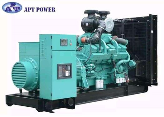
MAIN COMPONENTS OF A GENERATOR
A description of the main components of a generator is given below.
(1) Engine
The engine is the source of the input mechanical energy to the generator. The size of the engine is directly proportional to the maximum power output the generator can supply. There are several factors that you need to keep in mind while assessing the engine of your generator. The manufacturer of the engine should be consulted to obtain full engine operation specifications and maintenance schedules.
(a) Type of Fuel Used – Generator engines operate on a variety of fuels such as diesel, gasoline, propane (in liquefied or gaseous form), or natural gas
(b) Overhead Valve (OHV) Engines versus non-OHV Engines – OHV engines differ from other engines in that the intake and exhaust valves of the engine are located in the head of the engine’s cylinder as opposed to being mounted on the engine block. OHV engines have several advantages over other engines such as:
However, OHV-engines are also more expensive than other engines. (c) Cast Iron Sleeve (CIS) in Engine Cylinder – The CIS is a lining in the cylinder of the engine. It reduces wear and tear, and ensures durability of the engine.
(2) Alternator
The alternator, also known as the ‘genhead’, is the part of the generator that produces the electrical output from the mechanical input supplied by the engine. It contains an assembly of stationary and moving parts encased in a housing. The components work together to cause relative movement between the magnetic and electric fields, which in turn generates electricity. (a) Stator – This is the stationary component. It contains a set of electrical conductors wound in coils over an iron core.
(b) Rotor / Armature – This is the moving component that produces a rotating magnetic field in any one of the following three ways:
(i) By induction – These are known as brushless alternators and are usually used in large generators. (ii) By permanent magnets – This is common in small alternator units. (iii) By using an exciter – An exciter is a small source of direct current (DC) that energizes the rotor through an assembly of conducting slip rings and brushes.
The rotor generates a moving magnetic field around the stator, which induces a voltage difference between the windings of the stator. This produces the alternating current (AC) output of the generator.
The following are the factors that you need to keep in mind while assessing the alternator of a generator:
(a) Metal versus Plastic Housing – An all-metal design ensures durability of the alternator. Plastic housings get deformed with time and cause the moving parts of the alternator to be exposed. This increases wear and tear and more importantly, is hazardous to the user.
(b) Ball Bearings versus Needle Bearings – Ball bearings are preferred and last longer.
(c) Brushless Design – An alternator that does not use brushes requires less maintenance and also produces cleaner power.
(3) Fuel System
The fuel tank usually has sufficient capacity to keep the generator operational for 6 to 8 hours on an average. In the case of small generator units, the fuel tank is a part of the generator’s skid base or is mounted on top of the generator frame. Common features of the fuel system include the following:
(a) Pipe connection from fuel tank to engine – The supply line directs fuel from the tank to the engine and the return line directs fuel from the engine to the tank.
(b) Ventilation pipe for fuel tank – The fuel tank has a ventilation pipe to prevent the build-up of pressure or vacuum during refilling and drainage of the tank. When you refill the fuel tank, ensure metal-to-metal contact between the filler nozzle and the fuel tank to avoid sparks.
(c) Overflow connection from fuel tank to the drain pipe – This is required so that any overflow during refilling of the tank does not cause spillage of the liquid on the generator set.
(d) Fuel pump – This transfers fuel from the main storage tank to the day tank. The fuel pump is typically electrically operated.
(e) Fuel Water Separator / Fuel Filter – This separates water and foreign matter from the liquid fuel to protect other components of the generator from corrosion and contamination.
(f) Fuel Injector – This atomizes the liquid fuel and sprays the required amount of fuel into the combustion chamber of the engine.
(4) Voltage Regulator
As the name implies, this component regulates the output voltage of the generator. The mechanism is described below against each component that plays a part in the cyclical process of voltage regulation.
(1) Voltage Regulator: Conversion of AC Voltage to DC Current – The voltage regulator takes up a small portion of the generator’s output of AC voltage and converts it into DC current. The voltage regulator then feeds this DC current to a set of secondary windings in the stator, known as exciter windings.
(2) Exciter Windings: Conversion of DC Current to AC Current – The exciter windings now function similar to the primary stator windings and generate a small AC current. The exciter windings are connected to units known as rotating rectifiers.
(3) Rotating Rectifiers: Conversion of AC Current to DC Current – These rectify the AC current generated by the exciter windings and convert it to DC current. This DC current is fed to the rotor / armature to create an electromagnetic field in addition to the rotating magnetic field of the rotor / armature.
(4) Rotor / Armature: Conversion of DC Current to AC Voltage – The rotor / armature now induces a larger AC voltage across the windings of the stator, which the generator now produces as a larger output AC voltage.
This cycle continues till the generator begins to produce output voltage equivalent to its full operating capacity. As the output of the generator increases, the voltage regulator produces less DC current. Once the generator reaches full operating capacity, the voltage regulator attains a state of equilibrium and produces just enough DC current to maintain the generator’s output at full operating level.
(5) Cooling & Exhaust Systems
(a) Cooling System Continuous usage of the generator causes its various components to get heated up. It is essential to have a cooling and ventilation system to withdraw heat produced in the process. Raw/fresh water is sometimes used as a coolant for generators, but these are mostly limited to specific situations like small generators in city applications or very large units over 2250 kW and above. Hydrogen is sometimes used as a coolant for the stator windings of large generator units since it is more efficient at absorbing heat than other coolants. Hydrogen removes heat from the generator and transfers it through a heat exchanger into a secondary cooling circuit that contains de-mineralized water as a coolant.
(b) Exhaust System Exhaust fumes emitted by a generator are just like exhaust from any other diesel or gasonline engine and contain highly toxic chemicals that need to be properly managed. Hence, it is essential to install an adequate exhaust system to dispose of the exhaust gases. Exhaust pipes are usually made of cast iron, wrought iron, or steel. These need to be freestanding and should not be supported by the engine of the generator. Exhaust pipes are usually attached to the engine using flexible connectors to minimize vibrations and prevent damage to the generator’s exhaust system.
(6) Lubricating System
Since the generator comprises moving parts in its engine, it requires lubrication to ensure durability and smooth operations for a long period of time. The generator’s engine is lubricated by oil stored in a pump.
(7) Battery Charger
The start function of a generator is battery-operated. The battery charger keeps the generator battery charged by supplying it with a precise ‘float’ voltage. If the float voltage is very low, the battery will remain undercharged. If the float voltage is very high, it will shorten the life of the battery. Battery chargers are usually made of stainless steel to prevent corrosion. They are also fully automatic and do not require any adjustments to be made or any settings to be changed. The DC output voltage of the battery charger is set at 2.33 Volts per cell, which is the precise float voltage for lead acid batteries. The battery charger has an isolated DC voltage output that does interfere with the normal functioning of the generator.
(8) Control Panel
This is the user interface of the generator and contains provisions for electrical outlets and controls. The following article provides further details regarding the generator control panel. Different manufacturers have varied features to offer in the control panels of their units. Some of these are mentioned below.
(a) Electric start and shut-down – Auto start control panels automatically start your generator during a power outage, monitor the generator while in operation, and automatically shut down the unit when no longer required.
(b) Engine gauges – Different gauges indicate important parameters such as oil pressure, temperature of coolant, battery voltage, engine rotation speed, and duration of operation. Constant measurement and monitoring of these parameters enables built-in shut down of the generator when any of these cross their respective threshold levels.
(c) Generator gauges – The control panel also has meters for the measurement of output current and voltage, and operating frequency.
(d) Other controls – Phase selector switch, frequency switch, and engine control switch (manual mode, auto mode) among others.
(9) Main Assembly / Frame
All generators, portable or stationary, have customized housings that provide a structural base support. The frame also allows for the generated to be earthed for safety.
WORKING PRINCIPLES OF GENERATORS:
Generators are basically coils of electric conductors, normally copper wire, that are tightly wound onto a metal core and are mounted to turn around inside an exhibit of large magnets. An electric conductor moves through a magnetic field, the magnetism will interface with the electrons in the conductor to induce a flow of electrical current inside it.
The conductor coil and its core are called the armature, connecting the armature to the shaft of a mechanical power source, for example a motor, the copper conductor can turn at exceptionally increased speed over the magnetic field.
The point when the generator armature first starts to turn, then there is a weak magnetic field in the iron pole shoes. As the armature turns, it starts to raise voltage. Some of this voltage is making on the field windings through the generator regulator. This impressed voltage builds up stronger winding current, raises the strength of the magnetic field. The expanded field produces more voltage in the armature. This, in turn, make more current in the field windings, with a resultant higher armature voltage. At this time the signs of the shoes depended on the direction of flow of current in the field winding. The opposite signs will give current to flow in wrong direction.
TYPES OF GENERATORS
The generators are classified into two types.
1. AC generators 2. DC generators
1. AC GENERATORS
These are also called as alternators. It is the most important means of producing electrical power in many of the places since now days all the consumers are using AC. It works based on principle of the electromagnetic induction. These are of two types one is induction generator and other one is synchronous generator. The induction generator requires no separate DC excitation, regulator controls, frequency control or governor. This concept takes place when conductor coils turn in a magnetic field actuating a current and a voltage. The generators should run at a consistent speed to convey a stable AC voltage, even no load is accessible.
Synchronous generators are large size generators mainly used in power plants. These may be rotating field type or rotating armature type. In rotating armature type, armature is at rotor and field is at stator. Rotor armature current is taken through slip rings and brushes. These are limited due to high wind losses. These are used for low power output applications. Rotating field type of alternator is widely used because of high power generation capability and absence of slip rings and brushes.
It can be either 3 phase or two phase generators. A two-phase alternator produces two completely separate voltages. Each voltage may be considered as a single-phase voltage. Each is generated voltage completely independent of the other. The three-phase alternator has three single-phase windings spaced such that the voltage induced in any one phase is displaced by 120º from the other two. These can be connected either delta or wye connections. In Delta Connection each coil end is connected together to form a closed loop. A Delta Connection appears like the Greek Letter Delta (Δ). In Wye Connection one end of each coil connected together and the other end of each coil left open for external connections. A Wye Connection appears as the letter Y.
These generators are packaged with an engine or turbine to be used as a motor-generator set and used in applications like naval, oil and gas extraction, mining machinery, wind power plants etc.
Main parts of AC Generator (Alternator)
Obviously, consists of stator and rotor. But, the unlike other machines, in most of the alternators, field exciters are rotating and the armature coil is stationary.
Stator:
Unlike in DC machine stator of an alternator is not meant to serve path for magnetic flux. Instead, the stator is used for holding armature winding. The stator core is made up of lamination of steel alloys or magnetic iron, to minimize the eddy current losses.
Why Armature Winding Is Stationary in an Alternator?
At high voltages, it easier to insulate stationary armature winding, which may be as high as 30 kV or more. The high voltage output can be directly taken out from the stationary armature. Whereas, for a rotary armature, there will be large brush contact drop at higher voltages, also the sparking at the brush surface will occur. Field exciter winding is placed in rotor, and the low dc voltage can be transferred safely. The armature winding can be braced well, so as to prevent deformation caused by the high centrifugal force.
Rotor:
There are two types of rotor used in an AC generator / alternator:
1. Salient pole type: Salient pole type rotor is used in low and medium speed alternators. Construction of AC generator of salient pole type rotor is shown in the figure above. This type of rotor consists of large number of projected poles (called salient poles), bolted on a magnetic wheel. These poles are also laminated to minimize the eddy current losses. Alternators featuring this type of rotor are large in diameters and short in axial length. 2. Cylindrical type: Cylindrical type rotors are used in high speed alternators, especially in turbo alternators. This type of rotor consists of a smooth and solid steel cylinder havingg slots along its outer periphery. Field windings are placed in these slots. The DC supply is given to the rotor winding through the slip rings and and brushes arrangement.
Advantages of AC Generator
• These Generators are generally maintenance free, because of absence of brushes. • Easily step up and step down through transformers. • Transmission link size might be thinner because of step up feature • Size of the generator relatively smaller than DC machine • Losses are relatively less than DC machine • These Generator breakers are relatively smaller than DC breakers • For the large part, an AC motor has a very simple structure, because the only moving part it has is the rotor. for the large part, an AC motor has a very simple structure, because the only moving part it has is the rotor. • This also makes it easier to maintain these generators. • They have a quiet operation. • Cost of ownership is lower. • Longer lifespan compared to DC motors that have a commutator and carbon brushes that wear out over a period of time. These require regular replacement through the life of the system. • AC motors don’t have a smell that’s very typical of DC motors; in the latter, this is caused by components that are more prone to friction. • An AC generator allows users to covert its current to other voltages with the use of transformers; and these are compatible only with an AC generator and not with a DC generator. • This also makes it easier to maintain these generators. • They have a quiet operation. • Cost of ownership is lower.
Disadvantages of AC Generator
• These systems require additional insulation because of the greater voltages needed to supply a fixed level of power. • This poses a challenge when it comes to handling AC generators in a safe manner. • Working with Alternating current systems has some distinct risks and difficulties compared to what can be expected from DC motors. • While the use of a transformer is an advantage in AC systems, to a certain degree that can prove to be a limitation as well. This is because the motors then require a specific design which becomes a hindrance to a higher voltage discharge generated from one side. But since there is no other efficient method of generating high voltages, it becomes necessary to utilise transformers to ease the long-distance transmissions. These transmissions occur as soon as the lower voltage converts to the required higher levels. • Aside from this, Alternating Current power is more prone to overheating and sparks because it produces higher currents and this particular phenomenon can result in electrical shock as well as fires. The latter can cause a significant amount of damage to property and pose a threat to lives as well. • In addition to all these risks, an AC generator isn’t as durable as a DC generator.
2. DC GENERATORS
DC generator is typically found in off-grid applications. These generators give a seamless power supply directly into electric storage devices and DC power grids without novel equipment. The stored power is carries to loads through dc-ac converters. The DC generators could be controlled back to an unmoving speed as batteries tend to be stimulating to recover considerably more fuel. A dc generator is an electrical machine which converts mechanical energy into direct current electricity. This energy conversion is based on the principle of production of dynamically induced emf. This article outlines basic construction and working of a DC generator.
Construction of DC Machine:
Note: A DC generator can be used as a DC motor without any constructional changes and vice versa is also possible. Thus, a DC generator or a DC motor can be broadly termed as a DC machine. These basic constructional details are also valid for the construction of a DC motor. Hence, let’s call this point as construction of a DC machine instead of just ‘construction of a dc generator’.
A DC machine consists of two basic parts; stator and rotor. Basic constructional parts of a DC machine are described below.
1. Yoke: The outer frame of a dc machine is called as yoke. It is made up of cast iron or steel. It not only provides mechanical strength to the whole assembly but also carries the magnetic flux produced by the field winding.
2. Poles and pole shoes: Poles are joined to the yoke with the help of bolts or welding. They carry field winding and pole shoes are fastened to them. Pole shoes serve two purposes;
(i) they support field coils and (ii) spread out the flux in air gap uniformly.
3. Field winding: They are usually made of copper. Field coils are former wound and placed on each pole and are connected in series. They are wound in such a way that, when energized, they form alternate North and South poles.
4. Armature core: Armature core is the rotor of a dc machine. It is cylindrical in shape with slots to carry armature winding. The armature is built up of thin laminated circular steel disks for reducing eddy current losses. It may be provided with air ducts for the axial air flow for cooling purposes. Armature is keyed to the shaft.
5. Armature winding: It is usually a former wound copper coil which rests in armature slots. The armature conductors are insulated from each other and also from the armature core. Armature winding can be wound by one of the two methods; lap winding or wave winding. Double layer lap or wave windings are generally used. A double layer winding means that each armature slot will carry two different coils.
6. Commutator and brushes: Physical connection to the armature winding is made through a commutator-brush arrangement. The function of a commutator, in a dc generator, is to collect the current generated in armature conductors. Whereas, in case of a dc motor, commutator helps in providing current to the armature conductors. A commutator consists of a set of copper segments which are insulated from each other. The number of segments is equal to the number of armature coils. Each segment is connected to an armature coil and the commutator is keyed to the shaft. Brushes are usually made from carbon or graphite. They rest on commutator segments and slide on the segments when the commutator rotates keeping the physical contact to collect or supply the current.
Working Principle of DC Generator:
According to Faraday’s laws of electromagnetic induction, whenever a conductor is placed in a varying magnetic field (OR a conductor is moved in a magnetic field), an emf (electromotive force) gets induced in the conductor. The magnitude of induced emf can be calculated from the emf equation of dc generator. If the conductor is provided with a closed path, the induced current will circulate within the path. In a DC generator, field coils produce an electromagnetic field and the armature conductors are rotated into the field. Thus, an electromagnetically induced emf is generated in the armature conductors. The direction of induced current is given by Fleming’s right hand rule.
Need of a Split ring commutator:
According to Fleming’s right hand rule, the direction of induced current changes whenever the direction of motion of the conductor changes. Let’s consider an armature rotating clockwise and a conductor at the left is moving upward. When the armature completes a half rotation, the direction of motion of that particular conductor will be reversed to downward. Hence, the direction of current in every armature conductor will be alternating. If you look at the above figure, you will know how the direction of the induced current is alternating in an armature conductor. But with a split ring commutator, connections of the armature conductors also get reversed when the current reversal occurs. And therefore, we get unidirectional current at the terminals.
Types of DC Generator:
Each DC machine can act as a generator or a motor. Hence, this classification is valid for both DC generators and DC motors. DC machines are usually classified on the basis of their field excitation method.
This makes two broad categories of dc machines; (I) Separately excited and (II) Self-excited.
(I)Separately excited DC machines:
In separately excited dc machines, the field winding is supplied from a separate power source. That means the field winding is electrically separated from the armature circuit. Separately excited DC generators are not commonly used because they are relatively expensive due to the requirement of an additional power source or circuitry. They are used in laboratories for research work, for accurate speed control of DC motors with Ward-Leonard system and in few other applications where self-excited DC generators are unsatisfactory. In this type, the stator field flux may also be provided with the help of permanent magnets (such as in permanent magnet DC motors).
(II)Self-excited DC machines:
In this type, field winding and armature winding are interconnected in various ways to achieve a wide range of performance characteristics (for example, field winding in series or parallel with the armature winding). In a self-excited type of DC generator, the field winding is energized by the current produced by themselves. A small amount of flux is always present in the poles due to the residual magnetism. So, initially, current induces in the armature conductors of a dc generator only due to the residual magnetism. The field flux gradually increases as the induced current starts flowing through the field winding.
Self-excited machines can be further classified as :
1. Series wound dc machines –
In this type, field winding is connected in series with the armature winding. Therefore, the field winding carries whole of the load current (armature current). That is why series winding is designed with few turns of thick wire and the resistance is kept very low (about 0.5 Ohm).
2. Shunt wound dc machines –
Here, field winding is connected in parallel with the armature winding. Hence, the full voltage is applied across the field winding. Shunt winding is made with a large number of turns and the resistance is kept very high (about 100 Ohm). It takes only small current which is less than 5% of the rated armature current. Applications
* DC shunt wound generators are used for lighting purposes. * Used to charge the battery. * Providing excitation to the alternators.
3. Compound wound dc machines –
In this type, there are two sets of field winding. One is connected in series and the other is connected in parallel with the armature winding. Compound wound machines are further divided as –
* Short shunt – field winding is connected in parallel with only the armature winding * Long shunt – field winding is connected in parallel with the combination of series field winding and armature winding
Applications of DC Generators
The applications of the various types of DC Generators are as follows: –
Separately Excited DC Generators
* Separately excited DC Generators are used in laboratories for testing as they have a wide range of voltage output. * Used as a supply source of DC motors.
Shunt wound Generators * DC shunt wound generators are used for lighting purposes. * Used to charge the battery. * Providing excitation to the alternators.
Series Wound Generators * DC series wound generators are used in DC locomotives for regenerative braking for providing field excitation current. * Used as a booster in distribution networks. * Over compounded cumulative generators are used in lighting and heavy power supply. * Flat compounded generators are used in offices, hotels, homes, schools, etc. * Deferentially compounded generators are mainly used for arc welding purpose.
Advantages of DC Generator:
• Mainly DC machines have the wide variety of operating characteristics which can be obtained by selection of the method of excitation of the field winding.
• The output voltage can be smoothed by regularly arranging the coils around the armature. This leads to less fluctuations which is desirable for some steady state applications.
• No shielding need for radiation so cable cost will be less as compared to AC.GENERATORS: WORKING PRINCIPLE, CLASSIFICATION AND APPLICATIONS
Generator is a machine that converts mechanical energy into electrical energy. It works based on principle of faraday law of electromagnetic induction. The faradays law states that whenever a conductor is placed in a varying magnetic field, EMF is induced and this induced EMF is equal to the rate of change of flux linkages. This EMF can be generated when there is either relative space or relative time variation between the conductor and magnetic field. So the important elements of a generator are:
• Magnetic field • Motion of conductor in magnetic field
MAIN COMPONENTS OF A GENERATOR
A description of the main components of a generator is given below.
(1) Engine
The engine is the source of the input mechanical energy to the generator. The size of the engine is directly proportional to the maximum power output the generator can supply. There are several factors that you need to keep in mind while assessing the engine of your generator. The manufacturer of the engine should be consulted to obtain full engine operation specifications and maintenance schedules.
(a) Type of Fuel Used – Generator engines operate on a variety of fuels such as diesel, gasoline, propane (in liquefied or gaseous form), or natural gas
(b) Overhead Valve (OHV) Engines versus non-OHV Engines – OHV engines differ from other engines in that the intake and exhaust valves of the engine are located in the head of the engine’s cylinder as opposed to being mounted on the engine block. OHV engines have several advantages over other engines such as:
However, OHV-engines are also more expensive than other engines. (c) Cast Iron Sleeve (CIS) in Engine Cylinder – The CIS is a lining in the cylinder of the engine. It reduces wear and tear, and ensures durability of the engine.
(2) Alternator
The alternator, also known as the ‘genhead’, is the part of the generator that produces the electrical output from the mechanical input supplied by the engine. It contains an assembly of stationary and moving parts encased in a housing. The components work together to cause relative movement between the magnetic and electric fields, which in turn generates electricity. (a) Stator – This is the stationary component. It contains a set of electrical conductors wound in coils over an iron core.
(b) Rotor / Armature – This is the moving component that produces a rotating magnetic field in any one of the following three ways:
(i) By induction – These are known as brushless alternators and are usually used in large generators. (ii) By permanent magnets – This is common in small alternator units. (iii) By using an exciter – An exciter is a small source of direct current (DC) that energizes the rotor through an assembly of conducting slip rings and brushes.
The rotor generates a moving magnetic field around the stator, which induces a voltage difference between the windings of the stator. This produces the alternating current (AC) output of the generator.
The following are the factors that you need to keep in mind while assessing the alternator of a generator:
(a) Metal versus Plastic Housing – An all-metal design ensures durability of the alternator. Plastic housings get deformed with time and cause the moving parts of the alternator to be exposed. This increases wear and tear and more importantly, is hazardous to the user.
(b) Ball Bearings versus Needle Bearings – Ball bearings are preferred and last longer.
(c) Brushless Design – An alternator that does not use brushes requires less maintenance and also produces cleaner power.
(3) Fuel System
The fuel tank usually has sufficient capacity to keep the generator operational for 6 to 8 hours on an average. In the case of small generator units, the fuel tank is a part of the generator’s skid base or is mounted on top of the generator frame. Common features of the fuel system include the following:
(a) Pipe connection from fuel tank to engine – The supply line directs fuel from the tank to the engine and the return line directs fuel from the engine to the tank.
(b) Ventilation pipe for fuel tank – The fuel tank has a ventilation pipe to prevent the build-up of pressure or vacuum during refilling and drainage of the tank. When you refill the fuel tank, ensure metal-to-metal contact between the filler nozzle and the fuel tank to avoid sparks.
(c) Overflow connection from fuel tank to the drain pipe – This is required so that any overflow during refilling of the tank does not cause spillage of the liquid on the generator set.
(d) Fuel pump – This transfers fuel from the main storage tank to the day tank. The fuel pump is typically electrically operated.
(e) Fuel Water Separator / Fuel Filter – This separates water and foreign matter from the liquid fuel to protect other components of the generator from corrosion and contamination.
(f) Fuel Injector – This atomizes the liquid fuel and sprays the required amount of fuel into the combustion chamber of the engine.
(4) Voltage Regulator
As the name implies, this component regulates the output voltage of the generator. The mechanism is described below against each component that plays a part in the cyclical process of voltage regulation.
(1) Voltage Regulator: Conversion of AC Voltage to DC Current – The voltage regulator takes up a small portion of the generator’s output of AC voltage and converts it into DC current. The voltage regulator then feeds this DC current to a set of secondary windings in the stator, known as exciter windings.
(2) Exciter Windings: Conversion of DC Current to AC Current – The exciter windings now function similar to the primary stator windings and generate a small AC current. The exciter windings are connected to units known as rotating rectifiers.
(3) Rotating Rectifiers: Conversion of AC Current to DC Current – These rectify the AC current generated by the exciter windings and convert it to DC current. This DC current is fed to the rotor / armature to create an electromagnetic field in addition to the rotating magnetic field of the rotor / armature.
(4) Rotor / Armature: Conversion of DC Current to AC Voltage – The rotor / armature now induces a larger AC voltage across the windings of the stator, which the generator now produces as a larger output AC voltage.
This cycle continues till the generator begins to produce output voltage equivalent to its full operating capacity. As the output of the generator increases, the voltage regulator produces less DC current. Once the generator reaches full operating capacity, the voltage regulator attains a state of equilibrium and produces just enough DC current to maintain the generator’s output at full operating level.
(5) Cooling & Exhaust Systems
(a) Cooling System Continuous usage of the generator causes its various components to get heated up. It is essential to have a cooling and ventilation system to withdraw heat produced in the process. Raw/fresh water is sometimes used as a coolant for generators, but these are mostly limited to specific situations like small generators in city applications or very large units over 2250 kW and above. Hydrogen is sometimes used as a coolant for the stator windings of large generator units since it is more efficient at absorbing heat than other coolants. Hydrogen removes heat from the generator and transfers it through a heat exchanger into a secondary cooling circuit that contains de-mineralized water as a coolant.
(b) Exhaust System Exhaust fumes emitted by a generator are just like exhaust from any other diesel or gasonline engine and contain highly toxic chemicals that need to be properly managed. Hence, it is essential to install an adequate exhaust system to dispose of the exhaust gases. Exhaust pipes are usually made of cast iron, wrought iron, or steel. These need to be freestanding and should not be supported by the engine of the generator. Exhaust pipes are usually attached to the engine using flexible connectors to minimize vibrations and prevent damage to the generator’s exhaust system.
(6) Lubricating System
Since the generator comprises moving parts in its engine, it requires lubrication to ensure durability and smooth operations for a long period of time. The generator’s engine is lubricated by oil stored in a pump.
(7) Battery Charger
The start function of a generator is battery-operated. The battery charger keeps the generator battery charged by supplying it with a precise ‘float’ voltage. If the float voltage is very low, the battery will remain undercharged. If the float voltage is very high, it will shorten the life of the battery. Battery chargers are usually made of stainless steel to prevent corrosion. They are also fully automatic and do not require any adjustments to be made or any settings to be changed. The DC output voltage of the battery charger is set at 2.33 Volts per cell, which is the precise float voltage for lead acid batteries. The battery charger has an isolated DC voltage output that does interfere with the normal functioning of the generator.
(8) Control Panel
This is the user interface of the generator and contains provisions for electrical outlets and controls. The following article provides further details regarding the generator control panel. Different manufacturers have varied features to offer in the control panels of their units. Some of these are mentioned below.
(a) Electric start and shut-down – Auto start control panels automatically start your generator during a power outage, monitor the generator while in operation, and automatically shut down the unit when no longer required.
(b) Engine gauges – Different gauges indicate important parameters such as oil pressure, temperature of coolant, battery voltage, engine rotation speed, and duration of operation. Constant measurement and monitoring of these parameters enables built-in shut down of the generator when any of these cross their respective threshold levels.
(c) Generator gauges – The control panel also has meters for the measurement of output current and voltage, and operating frequency.
(d) Other controls – Phase selector switch, frequency switch, and engine control switch (manual mode, auto mode) among others.
(9) Main Assembly / Frame
All generators, portable or stationary, have customized housings that provide a structural base support. The frame also allows for the generated to be earthed for safety.
WORKING PRINCIPLES OF GENERATORS:
Generators are basically coils of electric conductors, normally copper wire, that are tightly wound onto a metal core and are mounted to turn around inside an exhibit of large magnets. An electric conductor moves through a magnetic field, the magnetism will interface with the electrons in the conductor to induce a flow of electrical current inside it.
The conductor coil and its core are called the armature, connecting the armature to the shaft of a mechanical power source, for example a motor, the copper conductor can turn at exceptionally increased speed over the magnetic field.
The point when the generator armature first starts to turn, then there is a weak magnetic field in the iron pole shoes. As the armature turns, it starts to raise voltage. Some of this voltage is making on the field windings through the generator regulator. This impressed voltage builds up stronger winding current, raises the strength of the magnetic field. The expanded field produces more voltage in the armature. This, in turn, make more current in the field windings, with a resultant higher armature voltage. At this time the signs of the shoes depended on the direction of flow of current in the field winding. The opposite signs will give current to flow in wrong direction.
TYPES OF GENERATORS
The generators are classified into two types.
1. AC generators 2. DC generators
1. AC GENERATORS
These are also called as alternators. It is the most important means of producing electrical power in many of the places since now days all the consumers are using AC. It works based on principle of the electromagnetic induction. These are of two types one is induction generator and other one is synchronous generator. The induction generator requires no separate DC excitation, regulator controls, frequency control or governor. This concept takes place when conductor coils turn in a magnetic field actuating a current and a voltage. The generators should run at a consistent speed to convey a stable AC voltage, even no load is accessible.
Synchronous generators are large size generators mainly used in power plants. These may be rotating field type or rotating armature type. In rotating armature type, armature is at rotor and field is at stator. Rotor armature current is taken through slip rings and brushes. These are limited due to high wind losses. These are used for low power output applications. Rotating field type of alternator is widely used because of high power generation capability and absence of slip rings and brushes.
It can be either 3 phase or two phase generators. A two-phase alternator produces two completely separate voltages. Each voltage may be considered as a single-phase voltage. Each is generated voltage completely independent of the other. The three-phase alternator has three single-phase windings spaced such that the voltage induced in any one phase is displaced by 120º from the other two. These can be connected either delta or wye connections. In Delta Connection each coil end is connected together to form a closed loop. A Delta Connection appears like the Greek Letter Delta (Δ). In Wye Connection one end of each coil connected together and the other end of each coil left open for external connections. A Wye Connection appears as the letter Y.
These generators are packaged with an engine or turbine to be used as a motor-generator set and used in applications like naval, oil and gas extraction, mining machinery, wind power plants etc.
Main parts of AC Generator (Alternator)
Obviously, consists of stator and rotor. But, the unlike other machines, in most of the alternators, field exciters are rotating and the armature coil is stationary.
Stator:
Unlike in DC machine stator of an alternator is not meant to serve path for magnetic flux. Instead, the stator is used for holding armature winding. The stator core is made up of lamination of steel alloys or magnetic iron, to minimize the eddy current losses.
Why Armature Winding Is Stationary in an Alternator?
At high voltages, it easier to insulate stationary armature winding, which may be as high as 30 kV or more. The high voltage output can be directly taken out from the stationary armature. Whereas, for a rotary armature, there will be large brush contact drop at higher voltages, also the sparking at the brush surface will occur. Field exciter winding is placed in rotor, and the low dc voltage can be transferred safely. The armature winding can be braced well, so as to prevent deformation caused by the high centrifugal force.
Rotor:
There are two types of rotor used in an AC generator / alternator:
1. Salient pole type: Salient pole type rotor is used in low and medium speed alternators. Construction of AC generator of salient pole type rotor is shown in the figure above. This type of rotor consists of large number of projected poles (called salient poles), bolted on a magnetic wheel. These poles are also laminated to minimize the eddy current losses. Alternators featuring this type of rotor are large in diameters and short in axial length. 2. Cylindrical type: Cylindrical type rotors are used in high speed alternators, especially in turbo alternators. This type of rotor consists of a smooth and solid steel cylinder having slots along its outer periphery. Field windings are placed in these slots. The DC supply is given to the rotor winding through the slip rings and brushes arrangement.
Advantages of AC Generator
• These Generators are generally maintenance free, because of absence of brushes. • Easily step up and step down through transformers. • Transmission link size might be thinner because of step up feature • Size of the generator relatively smaller than DC machine • Losses are relatively less than DC machine • These Generator breakers are relatively smaller than DC breakers • For the large part, an AC motor has a very simple structure, because the only moving part it has is the rotor. for the large part, an AC motor has a very simple structure, because the only moving part it has is the rotor. • This also makes it easier to maintain these generators. • They have a quiet operation. • Cost of ownership is lower. • Longer lifespan compared to DC motors that have a commutator and carbon brushes that wear out over a period of time. These require regular replacement through the life of the system. • AC motors don’t have a smell that’s very typical of DC motors; in the latter, this is caused by components that are more prone to friction. • An AC generator allows users to covert its current to other voltages with the use of transformers; and these are compatible only with an AC generator and not with a DC generator. • This also makes it easier to maintain these generators. • They have a quiet operation. • Cost of ownership is lower.
Disadvantages of AC Generator
• These systems require additional insulation because of the greater voltages needed to supply a fixed level of power. • This poses a challenge when it comes to handling AC generators in a safe manner. • Working with Alternating current systems has some distinct risks and difficulties compared to what can be expected from DC motors. • While the use of a transformer is an advantage in AC systems, to a certain degree that can prove to be a limitation as well. This is because the motors then require a specific design which becomes a hindrance to a higher voltage discharge generated from one side. But since there is no other efficient method of generating high voltages, it becomes necessary to utilise transformers to ease the long-distance transmissions. These transmissions occur as soon as the lower voltage converts to the required higher levels. • Aside from this, Alternating Current power is more prone to overheating and sparks because it produces higher currents and this particular phenomenon can result in electrical shock as well as fires. The latter can cause a significant amount of damage to property and pose a threat to lives as well. • In addition to all these risks, an AC generator isn’t as durable as a DC generator.
2. DC GENERATORS
DC generator is typically found in off-grid applications. These generators give a seamless power supply directly into electric storage devices and DC power grids without novel equipment. The stored power is carries to loads through dc-ac converters. The DC generators could be controlled back to an unmoving speed as batteries tend to be stimulating to recover considerably more fuel. A dc generator is an electrical machine which converts mechanical energy into direct current electricity. This energy conversion is based on the principle of production of dynamically induced emf. This article outlines basic construction and working of a DC generator.
Construction of DC Machine:
Note: A DC generator can be used as a DC motor without any constructional changes and vice versa is also possible. Thus, a DC generator or a DC motor can be broadly termed as a DC machine. These basic constructional details are also valid for the construction of a DC motor. Hence, let’s call this point as construction of a DC machine instead of just ‘construction of a dc generator’.
A DC machine consists of two basic parts; stator and rotor. Basic constructional parts of a DC machine are described below.
1. Yoke: The outer frame of a dc machine is called as yoke. It is made up of cast iron or steel. It not only provides mechanical strength to the whole assembly but also carries the magnetic flux produced by the field winding.
2. Poles and pole shoes: Poles are joined to the yoke with the help of bolts or welding. They carry field winding and pole shoes are fastened to them. Pole shoes serve two purposes;
(i) they support field coils and (ii) spread out the flux in air gap uniformly.
3. Field winding: They are usually made of copper. Field coils are former wound and placed on each pole and are connected in series. They are wound in such a way that, when energized, they form alternate North and South poles.
4. Armature core: Armature core is the rotor of a dc machine. It is cylindrical in shape with slots to carry armature winding. The armature is built up of thin laminated circular steel disks for reducing eddy current losses. It may be provided with air ducts for the axial air flow for cooling purposes. Armature is keyed to the shaft.
5. Armature winding: It is usually a former wound copper coil which rests in armature slots. The armature conductors are insulated from each other and also from the armature core. Armature winding can be wound by one of the two methods; lap winding or wave winding. Double layer lap or wave windings are generally used. A double layer winding means that each armature slot will carry two different coils.
6. Commutator and brushes: Physical connection to the armature winding is made through a commutator-brush arrangement. The function of a commutator, in a dc generator, is to collect the current generated in armature conductors. Whereas, in case of a dc motor, commutator helps in providing current to the armature conductors. A commutator consists of a set of copper segments which are insulated from each other. The number of segments is equal to the number of armature coils. Each segment is connected to an armature coil and the commutator is keyed to the shaft
“”Hit like button and share if you like the content …and don’t forget to follow for more updates”” Thank you.
First of all, I would like to confirm that AWD & 4WD are different from each other because many people think that both the terms are same but that is not correct.
I would like to mention some basic differences between AWD & 4WD:
In AWD (All wheel drive) system, power reaches to all the wheels at the same time but amount of power can be differon the wheels of a single set (front or rear) according to the conditions but in 4WD (4-wheel drive) system, we can control if we want the power on rear wheels or on front wheels only or we want the power on all the 4 wheels. Basically in 4WD, we can make our vehicle Front wheel drive, Rear wheel drive or 4 wheel drive as per our requirement but on one set of wheels (front or rear), power will be equal.
In AWD, 3 differentials are used to transmit the power to the wheels. 1st is between the front wheels, 2nd is between the rear wheels & 3rd one is between the set of front wheels and the rear wheels. But in 4WD, only 2 differentials are used for front and rear wheels.
AWD is consider as a safest but only for On-road conditions (where roads are in good condition) as Renault Duster, Subaru, Audi, Toyota has worked a lot on AWD. But 4WD is good for Off-road conditions because in all conditions, all wheels will get the equal amount of power. Toyota has also worked on 4WD.
In AWD, Differential manages the power & give more power to wheel which is free or which have less resistance or which wheel needs more power, which is beneficial on taking turns as one wheel will travel much more than the other then differential will provide more power to the more travelling wheel. But it will not beneficial when one wheel (front or rear) is in the air and other is stuck on the ground because it will give the power to the free wheel which will useless that time.
But in 4WD, equal amount of power will reach to all the wheels so it will not be good for On-road conditions & for smooth turns but it will be good for Off-road conditions because if one wheel got stuck and other will be in the air then 4WD will give equal amount of power on all the wheels, because of that the vehicle will come out of the stucked area.
Note:4WD and 4×4 is the same technology on the basic terms.
So, these are the Basic differences between AWD and 4WD.I hope this will be helpful to understand the difference between two & hope you’ll get your answer.
“”Hit like button and share if you like the content …and don’t forget to follow for more updates”” Thank you.
The Primary resource that needsto start these businesses and run them successfully is an initial monetary investment. I think you have a better idea why this money is important to start any mechanical company or manufacturing plant.
And Yes all these come with higher risk. So you need a better plan to survive if it gets down.
I work as a freelance 3D CAD product designer in a Fiverr and what I am seeing is there are so many opportunities for mechanical engineers to earn with their 3D modeling skills and start their own business.
Just have a look and see what suits you.
1.3D CAD Modeling
Creating a 3D model using computer-aided design software has a huge demand in the market. That was a time when only big design industry implements this 3D modeling, however, today with the boost of 3D Printing, Augmented reality and Virtual Reality people relying on customized 3D parts for their personal use.
So they move to the Freelance 3D Designers to get their work done in less time as they don’t want to hire anyone for the single task.
2.2D AutoCAD Drawing When it comes to 2D drawing, AutoCAD has all the tools to create any design in the form of a line drawing or we can say drafting. I have seen many people have a 3D design but they don’t get a 2D drawing from the designer.
They search for the person who can convert that design into two dimensions.2D drawing also extensively used in the patent filing and some government approval work. So there is a good scope of AutoCAD drawing expert as a freelancer.
3.3D Package Design Many people think that Packaging Design is the work of graphic designers only.
The reason Mechanical engineers don’t know now about the power of these Top Freelancing skills is that of graphics which are used in creating labels for the package. Let me tell you, you don’t have to get intimidated because many clients that come for freelance package design already have their logo and label.
This happen to me much time, I just have to make a package structure in software in 3D and update it with labels provided by clients. So these skills are in huge demand for working as a freelancer.
4.Mockup Design for Amazon Did you know many products that are on Amazon are not actually real but they are Realistic Mock-up of the actual product? The reason why they use is they want a visually appealing graphic of their product which cannot be attended by the DSLR.
Making use of High-quality 3D mock-ups, they get stunning visual and also motion graphics easily. If you can think E-commerce industry is the future then this is the future skills for freelancing.
5.Product Sketching When someone wants to design a product he first starts to create through a sketch of that design but what I know as a product designer, many clients only have an idea about how their product will function they don’t brainstorm about the aesthetics and ergonomics of their product.
For that, a product designer who is good in initial product sketching or I can say wireframing are in huge demand not only on the freelance website for also in open job markets.
6. Freehand Modeling This is same as 3D modeling but here you only have a picture of the product you need to do reverse engineering it by creating the exact and properly scaled 3D model. This skills also aligned with the Product Mock-up creation in some cases.
You need to guess the sizes of the product from the different angles with your sharp eyes and by proper assumption 3D model can be generated.I have seen many people have the actual physical product but for representation purpose, they need it in 3D format.
7.Stress Analysis and Simulation This Stream has open another vertical in the world of Freelancing. From Colleg grads to creative product design startups, all are serious about the importance of Mechanical Analysis and simulation to predict the failure of the product and make it better for the people.
They Always look for the freelancer who can analyze their product with software such as Ansys, Hypermesh, Nastran, Solidworks simulation and on some more analysis software. Also, the cost of per Product Simulation and analysis may vary from 50$ to 200$ for less complex product and starting from 300$ for complex products.
8.Full Product Design Creating a full product from scratch are most likely consist of initial brainstorming, sketching, 3D designing, Redesigning and Analysis. This are some big projects although they come in a less frequency on the freelance sites, their budget is huge like for example, someone needs full product design of the new Smartphone design with high-quality pleasing aesthetics.
This kind of project might range from 1000$ to 2400$ according to Fiverr. So if you know all the above-mentioned skills of design then you might get the single but high grossing shot.
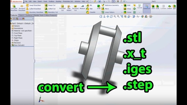
9.3D File Conversions Have you ever converted MS word file into Pdf? This skill is very adjacent to converting the 3D file into STL for 3D printing purpose or Converting from STL into IGES (Initial Graphics Exchange Specification) or into STEP (Standard for the Exchange of Product model data).
From my experience on Fiverr people who are in urgent need of this file conversion are intensively searching for the quick freelancer to this kind of work. So it better to be there for the people and collect the payment as quickly as possible. The average cost of this conversion is 7$ per part and 20$ per complex part.
For the wrap-up, just don’t think to procrastinate, learn these skills and get the edge on your freelancing career and show your true expertise.
Like and Share with your friends and if you don’t know about this skills, and want to learn these skills send your email id in comment .
Have a look on this blog too..”Quality which a mechanical engineer shoul have to get hired at VW,Audi,BMW”
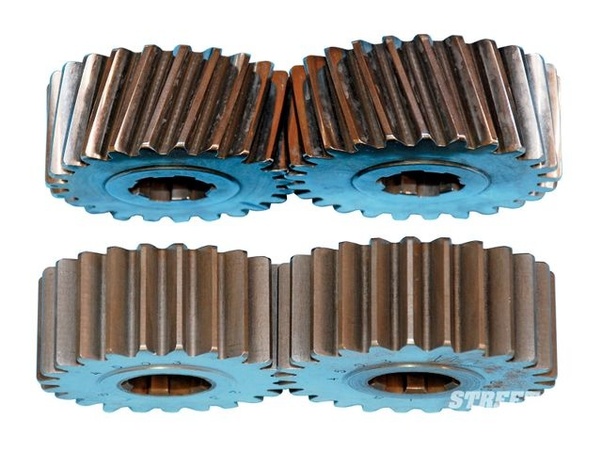
Reverse gears in vehicles use straight cut gears (bottom in photo) as opposed to the helically cut forward gears. (top in photo). Straight cut teeth essentially hit each other, which manifests as buzzing or rollover noise at higher rpms and has strictly one force component in the direction of rotation. Helically cut gears have more of a “glancing blow” or slicing behavior which has both radial and axial components of force.
Helical gears operate with a greater number of teeth meshing at the same time, resulting is greater load bearing area than their straight cut counterparts, resulting in less stress and are therefore used in street applications where greater torque is seen which is in the forward speeds. (In racing, this is not the case but it makes for a lighter gearbox. That is a separate discussion however.) In addition, helically cut gears are far quieter than straight cut. Likely at this point, a straight cut reverse gear is used strictly from a cost perspective since less complex hobbing operations are needed and less material needs to be used on the casting of the transmission, where normally, a helically cut reverse gear’s thrust loads under torque would have to be accommodated by a thicker wall.
“”Hit like button and share if you like the content …and don’t forget to follow for more updates””
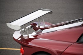
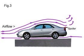
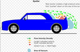
Spoilers are added to cars and other vehicles to make them more aerodynamic. Most are attached to the back of the vehicle, above the trunk, on the rear window, on the roof, or on the front. Various types and the positioning of a spoiler can do different things to improve a vehicle’s performance. However, the main reason people install these gadgets is to allow for better airflow over and around the vehicle, which in turn, creates better grip or traction on the road. Vehicles that run at high speeds often encounter control problems because, at high speeds, the increased airflow creates too much lift, which can be especially dangerous when the vehicle makes a turn, as this can make it fly off the road and lose control.
Benefits of a Car Spoiler :-
Installing a spoiler on a vehicle provides a variety of benefits for owners. The main benefits, perhaps, are for better traction and to add a sporty look, but also include other advantages, such as increased fuel efficiency, added visibility, reduced vehicle weight, and braking stability.
Benefit 1: Maintain Traction
The main benefit of installing a spoiler on a vehicle is to help it maintain traction at very high speeds. When a vehicle goes very fast (over 70 mph), the air pressure can lift the car, which makes it difficult to maneuver the car without the danger of having it spin out of control. Rear spoilers, in particular, push the back of the car down so the tires can grip the road better and increase stability.
Benefit 2: Increase Fuel Efficiency
Front car spoilers or air dams can increase gas mileage in some cars. Since these types of spoilers reduce the drag, instead of increasing it, by pushing the air around the vehicle, it does lower the amount of energy, or fuel, the car needs to burn to propel itself forward.
Benefit 3: Added Visibility
Another advantage of installing a rear spoiler on a vehicle is the added visibility, which means other drivers on the road can easily see the vehicle to help prevent rear-end collisions and other types of accidents. Certain spoilers, such as trunk cap spoilers, even have brake lights at eye level so the driver behind can easily be alerted when the vehicle is slowing down or braking.
Benefit 4: Reduce Weight
Believe it or not, a spoiler can reduce the weight of a vehicle. While this may seem counterintuitive, it makes sense in a way. The only thing keeping a vehicle stable on the road is its weight. Perhaps that is why many people have this perception that SUVs are much safer because their heavier mass keeps them steady. However, having a spoiler means that the car manufacturer can reduce the weight of the vehicle by using lighter materials or doing away with unnecessary weight without the worry that driving at high speeds causes the car to become unsteady and fly off the highway.
Benefit 5: Create a Stylish Look
Most car owners install spoilers as a fashion accessory, and spoilers do a pretty good job of making a vehicle look cool. This idea first became popular in the 1970s, when Porsche introduced the 911 Turbo, which featured whale tail spoilers on the back. Today, many cars come with built-in spoilers to evoke that sporty look, though many aftermarket spoilers are available for a wide variety of car makes and models.
Benefit 6: Increase Braking Stability
Adding spoilers that raise the downward force on the back of the vehicle not only increases traction, but the braking ability as well. Drivers have an easier time braking, even at high speeds, making driving even safer.